CNC tool crib and presetter records: control insert index counts, offset transfers, and breakage scrap holds
For stores, inventory control and production teams · Compare approaches
TL;DR — what you’ll learn
- Separate reusable tool holders (ADAPTIVE_HOLDER), consumable multi-edge carbide inserts (CUTTING_INSERT), and measured Tool Assemblies (TOOL_ASSEMBLY_ID) in your tool-crib and MES records so wear life is tracked per cutting edge rather than by bulk insert box issue.
- Transfer optical tool-presetter geometry offsets ($Z$ gauge length and $X/D$ radius) to the CNC controller via QR barcode scan, RFID chip, or DNC network rather than manual operator keypad entry, eliminating transposed-digit crash and plunge scrap.
- Enforce insert-edge contact-time and part-count ceilings (MAX_CUT_MIN_PER_EDGE) with automated sister-tool swap triggers before flank wear ($V_B$) crosses the catastrophic fracture threshold.
- Link every unplanned tool-breakage or spindle-overload alarm to an automatic backward suspect-part quarantine covering every part machined since the last passed dimensional inspection.

Illustrative factory raw-material stores and receiving counter; not a client facility.
In high-precision CNC turning and milling shops, treating cutting tools as generic shop-floor consumables ("issue 10 boxes of inserts to the lathe") leaves three major operational blind spots: operators indexing inserts too late (causing sudden carbide fracture and scrapped castings) or too early (wasting 30% of usable cutting edges), manual keypad typos when entering 6-digit tool-presetter offsets into the machine control, and failing to quarantine the 5 to 15 parts machined after the last quality check when a drill or boring bar chips mid-run. Distinct from M048 (which governs multi-cavity injection moulds and stamping dies) and M037 (metrology gauge calibration), this guide (M106) covers CNC tool-crib assembly serialization, optical presetter offset transfer, insert edge-index life tracking, and tool-breakage suspect-part containment.
Scope and quality-standard boundary
This article defines the ERP/MES tool-crib, presetter-offset, and nonconforming-part containment record architecture for CNC machining operations:
- What this workflow governs: Tracking serialized tool assemblies (
Holder + Collet + Insert Lot), logging optical presetter $Z/X$ geometry and runout values, counting in-cut minutes/parts per indexable cutting edge, managing sister-tool swaps, and bounding suspect-part quarantine batches upon tool breakage. - What this workflow does not replace: It does not prescribe cutting speeds, feeds, coolant chemistry, or CNC G-code post-processor programming. Tool data representation, wear testing, and suspect-material containment should align with industry standards including ISO 13399 (Cutting Tool Data Representation and Exchange), ISO 3685 / ISO 8688 (Tool-Life Testing), and automotive quality management requirements under IATF 16949 (Sections 8.5.1.5 and 8.7).
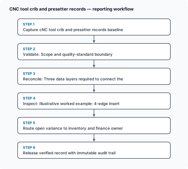
Bounded tool crib management software verification and exception-routing workflow
Follow the workflow below, or open its complete text version.
Read the complete workflow as text
- Capture tool crib management softwar baseline record → Verify revision, unit Basis and cutoff alignment
- Verify revision, unit Basis and cutoff alignment → Run deterministic reconciliation and tolerance check
- Run deterministic reconciliation and tolerance check → Quarantine mismatched or unapproved lines
- Quarantine mismatched or unapproved lines → Route exception to named domain and finance owner
- Route exception to named domain and finance owner → Release verified record with immutable audit trail
Three data layers required to connect the tool crib to the CNC spindle
Using standard ERP workstation and quality structures (such as ERPNext Workstations and Quality Inspection records) alongside shop-floor tool management, structure cutting-tool records across three distinct levels per ISO 13399:
- Component Layer (Holders, Collets, and Insert Lots):
- Tool Holder / Arbor (
HLD-BT40-088): Reusable asset tracked by pull-stud inspection cycles, taper cleanliness, and maximum dynamic runout ($\text{TIR} \le 0.003\text{ mm}$). - Indexable Insert / Solid Carbide Tool (
INS-CNMG120408-LOT92): Consumable tracked by supplier substrate/coating lot number and number of usable cutting corners ($N_{\text{edges}} = 2, 3, 4, \text{ or } 8$).
- Tool Holder / Arbor (
- Assembled & Presetter-Verified Layer (
TA-402-REV3): When the tool crib builds a tool assembly and measures it on an optical presetter, the system records the exact gauge length ($Z_{\text{offset}}$), diameter/radius ($X_{\text{offset}}$), nose radius ($R$), and measured runout ($\text{TIR}$) against a unique assembly instance ID. Scanning the assembly's 2D matrix code or Balluff RFID tag at the CNC magazine loads these exact micron-level offsets into the controller tool table without human keystrokes. - In-Spindle Edge Life & Breakage Containment Layer: Each indexable corner ($e \in {1 \dots N_{\text{edges}}}$) carries a validated safe cutting-time budget ($T_{\text{safe_edge}}$, in net spindle-in-cut minutes) or part-count cap ($P_{\text{safe_edge}}$): $$P_{\text{safe_edge}} = \left\lfloor \frac{T_{\text{safe_edge}}}{t_{\text{cut_per_part}}} \right\rfloor$$ When the active edge reaches $P_{\text{safe_edge}}$, the CNC swaps to a pre-measured sister tool in the magazine and prompts the operator to index the insert to the next corner at the end of the cycle.
Scroll horizontally to see all columns.
| Control Gate | Record & Identifier | Failure Mode Without Gate | Mandatory MES / Tool-Crib Action |
|---|---|---|---|
| 1. Tool Assembly & Runout Check | TOOL_ASSEMBLY_ID + Presetter $\text{TIR}$ ($\mu\text{m}$) |
Worn collet ($\text{TIR} over 12,\mu\text{m}$) halves carbide tool life and chatters finish | Block presetter label print if measured runout exceeds holder spec (e.g., $ over 5,\mu\text{m}$) |
| 2. Offset Transfer to CNC | Presetter $Z / X / R$ payload + QR/RFID/DNC checksum | Operator types 184.162 instead of 184.612 ($-0.450\text{ mm}$ error), crashing first part |
Require barcode/DNC offset load + mandatory single-block dry distance-to-go check |
| 3. Edge Index Life Counter | EDGE_INDEX ($1..N_{\text{edges}}$) + net in-cut minutes |
Operator flips back to an already-used chipped corner or runs past flank-wear limit | Require operator to confirm corner index (Edge 1 - over Edge 2) and log worn-edge reason code |
| 4. Breakage Suspect Quarantine | Last passed gauge timestamp ($n_{\text{pass}}$) to breakage cycle ($n_{\text{break}}$) | Operator replaces broken insert and mixes 8 out-of-tolerance parts into good bin | Automatically quarantine parts $(n_{\text{pass}} + 1)$ through $n_{\text{break}}$ under TOOL_BREAK_HOLD |
Illustrative worked example: 4-edge insert life accounting, offset typo prevention, and breakage containment
Illustrative CNC machining scenario using synthetic figures to demonstrate tool-life and suspect-lot containment arithmetic; not a client case study.
An automotive Tier-1 machining cell runs a CNC turning centre (CNC-LATHE-07) rough-and-semi-finishing forged steel transmission shafts (WO-SHAFT-910, batch size $240\text{ parts}$) using a 4-edge rhombic carbide insert (CNMG-120408, $N_{\text{edges}} = 4$ usable corners per insert).
Step 1: Compute per-edge and per-insert part capacity.
- Net spindle-in-cut contact time per shaft ($t_{\text{cut}}$): $2.80\text{ minutes/part}$ (out of a $4.00\text{-minute}$ floor-to-floor cycle).
- Validated safe cutting time per edge before flank wear $V_B$ reaches $0.25\text{ mm}$ ($T_{\text{safe_edge}}$): $42.0\text{ cutting minutes}$.
- Safe parts per cutting edge ($P_{\text{safe_edge}}$): $$P_{\text{safe_edge}} = \frac{42.0\text{ min/edge}}{2.80\text{ min/part}} = 15.0\text{ parts/edge}$$
- Total parts per 4-edge insert ($P_{\text{insert}}$) and standard insert consumption for the $240\text{-part}$ work order: $$P_{\text{insert}} = 4\text{ edges} \times 15.0\text{ parts/edge} = 60.0\text{ parts/insert};\left(168.0\text{ cutting minutes/insert}\right)$$ $$\text{Standard Inserts Required for 240 Parts} = \frac{240\text{ parts}}{60.0\text{ parts/insert}} = 4.0\text{ inserts } (16\text{ cutting edges})$$
Step 2: Prevent optical presetter offset transposition error.
Before the run, the tool crib mounts a fresh insert into holder TA-402 and measures it on the optical presetter:
- Measured presetter gauge length ($Z_{\text{actual}}$): $184.612\text{ mm}$
- Measured presetter radius ($X_{\text{actual}}$): $39.984\text{ mm}$
If an operator manually types the $Z$ offset into the lathe keypad and transposes two digits (184.162 mm instead of 184.612 mm), the resulting offset error is:
$$\Delta Z_{\text{typo}} = 184.162\text{ mm} - 184.612\text{ mm} = -0.450\text{ mm}$$
Because the controller believes the tool tip is $0.450\text{ mm}$ shorter than reality, the turret drives the tool $0.450\text{ mm}$ too deep into the shaft shoulder, scrapping the forging (toleranced at $\pm 0.025\text{ mm}$). Scanning the presetter's 2D QR label directly into the CNC offset register eliminates the $-0.450\text{ mm}$ transposition risk.
Step 3: Bound the suspect-part quarantine window after a premature Edge 3 fracture.
During the run on Insert #1:
- Edge 1 completes Parts #1–#15 ($42.0\text{ cut min}$) $\implies$ indexed cleanly; Part #15 passes in-process air-gauge inspection.
- Edge 2 completes Parts #16–#30 ($42.0\text{ cut min}$) $\implies$ indexed cleanly; Part #30 passes in-process inspection at
10:12. - Edge 3 starts at Part #31 (
10:14). Due to a hard forging scale inclusion, the carbide nose fractures during the cut on Part #39 at10:41(after $8.6\text{full/partial parts} \approx 24.1\text{ cutting minutes}$ on Edge 3), tripping the CNC spindle-load monitor.
Under IATF 16949 Section 8.7 suspect-product containment rules, the MES automatically calculates the quarantine population between the last verified good inspection ($n_{\text{pass}} = 30$) and the breakage cycle ($n_{\text{break}} = 39$):
$$N_{\text{suspect}} = n_{\text{break}} - n_{\text{pass}} = 39 - 30 = 9\text{ suspect parts } (\text{Parts #31 through #39})$$
Scroll horizontally to see all columns.
| Edge / Event Sequence | Part Serial Range | In-Cut Time ($\text{min}$) | Last Verified Gauge Check | Breakage / Wear Outcome | MES Disposition & Inventory Status |
|---|---|---|---|---|---|
| Insert #1 — Edge 1 | #001 – #015 ($15\text{ pcs}$) |
$42.0\text{ min}$ | #015 PASS (09:10) |
Normal flank wear ($V_B = 0.22\text{ mm}$) | RELEASED to downstream grinding |
| Insert #1 — Edge 2 | #016 – #030 ($15\text{ pcs}$) |
$42.0\text{ min}$ | #030 PASS (10:12) |
Normal flank wear ($V_B = 0.24\text{ mm}$) | RELEASED to downstream grinding |
| Insert #1 — Edge 3 (Fracture) | #031 – #039 ($9\text{ pcs}$) |
$24.1\text{ min}$ | None after #030 |
Spindle overload trip on #039 (10:41) |
QUARANTINED (TOOL_BREAK_HOLD): 100% gauge sort required |
100% dimensional sorting of the $9\text{ quarantined parts}$ (#031–#039) confirms that Parts #031–#037 ($7\text{ pcs}$) are within tolerance, Part #038 ($1\text{ pc}$) is oversized and salvageable by rework pass, and Part #039 ($1\text{ pc}$) has a gouged shoulder and is scrapped.
Workflow, owner roles, exceptions, and recovery controls
Scroll horizontally to see all columns.
| Workflow Stage | Accountable Owner | Required System Record | Exception Trigger | Recovery & Escalation Control |
|---|---|---|---|---|
| 1. Tool Crib Build & Presetting | Tool Crib Technician | TOOL_ASSEMBLY_ID, holder ID, insert lot, presetter $Z/X/R$ and $\text{TIR}$ |
Runout $\text{TIR} over 0.005\text{ mm}$ or wrong nose radius insert fitted | Disassemble collet/holder, clean taper, replace collet or insert, and re-measure before printing QR tag |
| 2. Magazine Load & Offset Sync | CNC Setup Operator | Scanned TOOL_ASSEMBLY_ID QR/RFID + pocket number + wear offset reset to $0.000$ |
Operator attempts manual gross geometry edit $ over 0.100\text{ mm}$ at CNC panel | Lock gross geometry table (G10); allow operator micro-wear comp only within $\pm 0.050\text{ mm}$ window |
| 3. Edge Indexing & Sister Swap | CNC Operator | Edge counter reaches $P_{\text{safe_edge}} = 15\text{ parts}$; sister tool engaged | Operator clears counter without indexing corner or logs $ under 50%$ expected edge life repeatedly | Require worn-edge reason code (CHIPPING, CHATTER, SCALE); alert manufacturing engineer if 3 consecutive edges fail early |
| 4. Breakage Alarm & Suspect Hold | Quality Inspector & Cell Lead | Spindle load trip timestamp, last passed inspection serial $n_{\text{pass}}$, suspect range $(n_{\text{pass}}+1)..n_{\text{break}}$ | Machine restarted before suspect parts #31–#39 are physically moved to quarantine bin |
Interlock cycle-start reset on QA badge scan confirming all $N_{\text{suspect}}$ parts are tagged in TOOL_BREAK_HOLD |
Bounded pilot and implementation check
Pilot closed-loop presetter offset transfer and breakage suspect-lot containment on 2 CNC turning or milling centres over 3 weeks:
- Pilot boundary: Track the top 6 critical roughing and finishing tool assemblies, recording presetter $Z/X$ payloads, per-edge part counts, and any premature breakage events.
- Baseline capture: Review the prior 60 days of first-piece setup scrap caused by offset entry errors, unexplained carbide insert over-consumption, and downstream assembly rejections from undetected tool chipping.
- Acceptance criteria: Zero first-piece scrap events from manual offset transposition on QR/DNC-loaded tools; 100% of insert issues reconcile against logged edge index counts within $\pm 5%$; 100% of unplanned tool breakages generate an automatic backward suspect-part quarantine record back to the last passed gauge check.
- Stop condition: If legacy CNC controllers cannot ingest DNC/QR offset strings directly, enforce a two-person verification scan (or presetter-label-to-screen photo log) on all geometry offset changes exceeding $0.050\text{ mm}$ before starting the cut.
Recommended next actions.
- Assign unique
TOOL_ASSEMBLY_IDtags to built holders and track insert life per cutting edge: Stop expensing inserts at box issue without recording how many parts or cutting minutes each corner delivered. - Automate presetter-to-CNC geometry offset transfer: Use 2D QR codes, RFID chips, or DNC transfers to load $Z$ length and $X$ diameter offsets and lock out large manual keypad edits.
- Set preventive sister-tool swap triggers at $T_{\text{safe_edge}}$: Swap tools based on actual spindle-in-cut minutes before flank wear causes catastrophic carbide fracture.
- Automate backward suspect-part quarantine on every tool breakage: Whenever a tool breaks at Part $n_{\text{break}}$, automatically hold Parts $(n_{\text{pass}} + 1)$ through $n_{\text{break}}$ in ERP/MES until 100% dimensional sorting clears.
Frequently Asked Questions
How should CNC machining plants track carbide insert index counts, optical tool-presetter offsets, and premature tool-breakage scrap holds between the tool crib and machine controllers?.
Teams should govern tool crib management software by linking every transaction to its source evidence, timestamp, and assigned owner before permitting downstream posting. Distinct from M048 (mould/die cavity shot tracking); M106 covers cutting-tool assemblies, presetter gauge-length offsets, sister-tool auto-swap limits, and linking sudden insert breakage to quarantine of the last N machined parts. Rather than relying on informal spreadsheet overrides, the workflow enforces a documented verification gate and preserves the original observation whenever a correction is recorded.
How does cnc tool management handle exceptions and mismatches?.
When a discrepancy occurs during cnc tool management, the system routes the blocked record into an owned exception queue rather than silently dropping or auto-adjusting the balance. Assigned operational, quality, and finance owners must review and approve exceptions before posting. Each exception retains the original quantity, date, and counterparty reference until the designated reviewer resolves the variance with supporting evidence.
What should teams test before automating tool life tracking?.
Before scaling tool life tracking, run a bounded pilot using historical records that include partial receipts, late updates, duplicate messages, and rejected lines. Verify that the integration preserves idempotency, maintains a clear segregation of duties between operational entry and financial approval, and produces an auditable trail for every state transition.
Compare this workflow with your current setup
Share the step that takes the most manual work, the systems involved and the exceptions your team handles. That gives us a concrete starting point for comparing approaches.
Sources and further reading
Sources checked 15 October 2026. Worked examples and workflow diagrams are original illustrations, not reported client results.

