Wire and cable extrusion records: control spark-test fault cuts, drum lengths, and copper mass balance
For production managers, planners and plant leaders · Compare approaches
TL;DR — what you’ll learn
- Record exact metre-mark coordinates ($X_{\text{fault}}$) from inline high-voltage spark testers ([IEC 62230](https://webstore.iec.ch/en/publication/6607)) and laser diameter gauges against every serialized master take-up reel (MASTER_REEL_ID) so insulation pinholes and neck-downs are automatically mapped before the rewinding/cutting line.
- Run a 1D Fault-Aware Drum Cutting Optimization before rewinding master reels into customer dispatch drums: split the master reel at every quarantined spark-fault coordinate first, then pack customer drum lengths ($1,000\text{ m}$, $500\text{ m}$, $250\text{ m}$) into the fault-free sub-segments to minimize unshippable short ends (remnant tails).
- Reconcile dual units of measure ($\text{Metres}$ and $\text{Kilograms}$) on both copper conductor drawing and polymer insulation extrusion, locking conductor cross-section just inside the [IEC 60228](https://webstore.iec.ch/en/publication/1110) maximum $20^\circ\text{C}$ DC resistance ceiling ($\Omega/\text{km}$) so the plant never gives away $2\%\text{–}3\%$ excess copper weight per kilometre.
- Print sequential sheath length start/end markings ($M_{\text{start}} \to M_{\text{end}}$) on every customer drum certificate and wooden/steel returnable drum tag.

Illustrative manufacturing inspection room and machine shop floor; not a client facility.
In wire and cable manufacturing, ERP systems that track cables purely by weight ($\text{kg}$) or purely by aggregate length ($\text{m}$) fail on the shop floor: an inventory ledger showing "$4,200\text{ m}$ of $3\times 2.5\text{ mm}^2$ control cable in stock" cannot fulfil four $1,000\text{ m}$ customer drum orders if that $4,200\text{ m}$ actually sits as seven fragmented $600\text{ m}$ reels—or if an inline spark-test pinhole at the $1,540\text{ m}$ mark forces a mandatory cutout right in the middle of the second $1,000\text{ m}$ drum. Distinct from M034 (2D/width slitting of flexible packaging film reels), this guide (M115) specifies inline spark-fault coordinate mapping, fault-aware 1D drum-length cutting optimization, copper resistance-to-weight reconciliation, and serialized cable drum inventory governance.
Scope and cable standards boundary
This article defines the ERP/MES reel-coordinate mapping, 1D cut optimization, and dual-UOM mass-balance architecture for wire and cable plants:
- What this workflow governs: Capturing inline encoder metre marks for spark-test and diameter-gauge faults on master take-up reels, computing optimal cut plans into continuous customer drum lengths, tracking copper linear density ($\text{kg/km}$) vs DC resistance ($\Omega/\text{km}$), and managing serialized cable drums (
DRUM_ID). - What this workflow does not replace: It does not replace extruder screw design, cross-linking (CV tube) curing calculations, or high-voltage Routine Test chamber protocols. Cable testing and conductor rules should align with IEC 62230 / UL 2556 (Electric Cables — Spark-Test Method), IEC 60228 (Conductors of Insulated Cables), and IEC 60502 / BS EN 50525 (Sequential Length Marking and Delivery Lengths).
Bounded wire and cable erp verification and exception-routing workflow
Follow the workflow below, or open its complete text version.
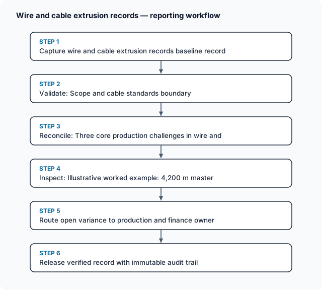
Read the complete workflow as text
- Capture wire and cable erp baseline record → Verify revision, unit Basis and cutoff alignment
- Verify revision, unit Basis and cutoff alignment → Run deterministic reconciliation and tolerance check
- Run deterministic reconciliation and tolerance check → Quarantine mismatched or unapproved lines
- Quarantine mismatched or unapproved lines → Route exception to named domain and finance owner
- Route exception to named domain and finance owner → Release verified record with immutable audit trail
Three core production challenges in wire and cable ERP/MES
- Inline Spark-Test Pinhole Coordinates Breaking Continuous Lengths: An extrusion line runs continuously at $150\text{–}600\text{ m/min}$ and cannot stop mid-extrusion without burning polymer in the crosshead die and creating a massive scrap lump. Instead, when the inline AC/DC high-frequency spark tester (IEC 62230) detects an insulation breakdown or the laser micrometer detects a thin-wall excursion, the line PLC logs the exact encoder coordinate ($X_{\text{fault}}$, in metres from reel start) onto the master reel's electronic traveler. At the downstream rewinding and cutting line, the drive automatically slows down and stops at $X_{\text{fault}} - 1.0\text{ m}$ so the operator can cut out the $2.0\text{ m}$ defective zone.
- 1D Cutting Stock Problem Across Fault-Split Segments: Once fault cutouts divide a master reel of length $L_{\text{master}}$ into $m$ fault-free contiguous segments ($S_1, S_2, \dots, S_m$), each segment $S_j$ must be partitioned into ordered customer drum lengths ($d_k \in {1000\text{ m}, 500\text{ m}, 250\text{ m}, \text{custom}}$ plus a small positive cutting tolerance $\delta_{\text{tol}} \approx +2\text{ m}$ to prevent short-delivery claims) to minimize unshippable remnant tails: $$\min \sum_{j=1}^{m} \left(S_j - \sum_{k} n_{jk},(d_k + \delta_{\text{tol}})\right) \quad \text{subject to} \quad \sum_{k} n_{jk},(d_k + \delta_{\text{tol}}) \le S_j$$
- Copper Giveaway vs IEC 60228 DC Resistance Compliance: Copper accounts for $60%\text{–}80%$ of a power cable's BOM cost. Under IEC 60228, conductor acceptance is governed primarily by maximum DC resistance at $20^\circ\text{C}$ ($R_{20}$, in $\Omega/\text{km}$) rather than nominal geometric cross-section alone: $$R_{20} = R_{T} \times \frac{1}{1 + \alpha_{20}(T - 20^\circ\text{C})} \le R_{20,\text{max}}$$ where $\alpha_{20} = 0.00393,\text{K}^{-1}$ for annealed copper. If wire-drawing dies wear large by just $+1.6%$ in diameter ($+3.2%$ in area), the cable easily passes $R_{20}$, but the plant silently gives away $ over 2\text{ kg}$ of free copper per kilometre without being able to bill the customer for extra weight.
Illustrative worked example: 4,200 m master reel spark-fault splitting, drum cut optimization, and copper giveaway audit
Illustrative wire-and-cable production scenario using synthetic figures to demonstrate fault-coordinate cutting and copper mass-balance arithmetic; not a client case study.
A cable plant extrudes and sheaves a $4,200.0\text{ m}$ master reel (REEL-EXT-704) of $0.6/1\text{ kV}$ $3 \times 2.5\text{ mm}^2$ XLPE/PVC control cable.
Step 1: Split master reel at the inline spark-test fault coordinate.
During jacket extrusion, the $6\text{ kV}$ AC inline spark tester logs a single insulation breakdown at encoder mark $X_{\text{fault}} = 1,540.0\text{ m}$. Quality rules require excising $\pm 1.0\text{ m}$ around any spark fault ($2.0\text{ m}$ cutout from $1,539.0\text{ m}$ to $1,541.0\text{ m}$), dividing REEL-EXT-704 into two continuous fault-free segments:
- Segment A (
0.0 mto1,539.0 m): $S_A = 1,539.0\text{ m}$ - Excised Spark-Fault Scrap (
1,539.0 mto1,541.0 m): $2.0\text{ m}$ - Segment B (
1,541.0 mto4,200.0 m): $S_B = 4,200.0 - 1,541.0 = 2,659.0\text{ m}$ - Total Fault-Free Cable Available: $1,539.0 + 2,659.0 = 4,198.0\text{ m}$
Step 2: Optimize customer drum cutting across Segments A and B.
Open sales orders require continuous non-spliced drums of $1,000\text{ m}$, $500\text{ m}$, and $250\text{ m}$. To guarantee zero short-length claims after thermal contraction and end-cap trimming, the rewinder adds $\delta_{\text{tol}} = +2.0\text{ m}$ per cut drum ($1,002.0\text{ m}$, $502.0\text{ m}$, and $252.0\text{ m}$ physical cuts):
- Without Fault-Aware Planning (Naive sequential cutting): An operator trying to wind two $1,000\text{ m}$ drums sequentially hits the $1,539.0\text{ m}$ spark fault $537\text{ m}$ into the second drum—scrapping or downgrading a $537\text{ m}$ odd length that cannot fulfil a $1,000\text{ m}$ order.
- With MES Fault-Aware Cut Plan:
- From Segment A ($1,539.0\text{ m}$):
- Cut
DRUM-704-01($1,000\text{ m}$ billed / $1,002.0\text{ m}$ cut): Sheath marks0000 m–1002 m - Cut
DRUM-704-02($500\text{ m}$ billed / $502.0\text{ m}$ cut): Sheath marks1002 m–1504 m - Segment A Remnant Tail: $1,539.0 - (1,002.0 + 502.0) = \mathbf{35.0\text{ m}}$ (
1504 m–1539 m, routed to copper granulation recovery).
- Cut
- From Segment B ($2,659.0\text{ m}$):
- Cut
DRUM-704-03($1,000\text{ m}$ billed / $1,002.0\text{ m}$ cut): Sheath marks1541 m–2543 m - Cut
DRUM-704-04($1,000\text{ m}$ billed / $1,002.0\text{ m}$ cut): Sheath marks2543 m–3545 m - Cut
DRUM-704-05($250\text{ m}$ billed / $252.0\text{ m}$ cut): Sheath marks3545 m–3797 m - Cut
DRUM-704-06($250\text{ m}$ billed / $252.0\text{ m}$ cut): Sheath marks3797 m–4049 m - Segment B Remnant Tail: $2,659.0 - (2 \times 1,002.0 + 2 \times 252.0) = 2,659.0 - 2,508.0 = \mathbf{151.0\text{ m}}$ (
4049 m–4200 m, booked intoSTOCK-ODD-LENGTHfor a $150\text{ m}$ wholesale cut-length counter order).
- Cut
- Total First-Quality Yield: $4,012.0\text{ m}$ on 6 standard drums ($4,000.0\text{ m}$ billed) + $151.0\text{ m}$ salable counter reel = $4,163.0\text{ m}$ ($99.12%$ of fault-free length).
- From Segment A ($1,539.0\text{ m}$):
Step 3: Reconcile copper conductor mass against $20^\circ\text{C}$ DC resistance.
Under IEC 60228, Class 2 stranded $2.5\text{ mm}^2$ plain copper conductor has a maximum permissible DC resistance at $20^\circ\text{C}$ of $R_{20,\text{max}} = 7.41,\Omega/\text{km}$:
- Target Resistance-Controlled Drawing Window: $R_{20} = 7.34\text{–}7.38,\Omega/\text{km}$, requiring $65.95\text{ kg/km}$ of copper across the 3 cores.
- Uncontrolled Worn-Die Run ($R_{20} = 7.12,\Omega/\text{km}$): Consumes $68.10\text{ kg/km}$ of copper ($+2.15\text{ kg Cu/km}$ giveaway).
- Copper Saved Across
REEL-EXT-704($4.20\text{ km}$) by Die-Resistance Control: $$\Delta M_{\text{Cu_saved}} = (68.10 - 65.95)\text{ kg/km} \times 4.20\text{ km} = 2.15 \times 4.20 = 9.03\text{ kg copper saved per master reel}$$
Scroll horizontally to see all columns.
| Drum / Segment ID | Sheath Metre Marks | Physical Cut ($\text{m}$) | Billed Length ($\text{m}$) | $20^\circ\text{C}$ DC Resistance ($R_{20}$) | High-Voltage Drum Test | ERP Inventory Status |
|---|---|---|---|---|---|---|
DRUM-704-01 (Seg A) |
0000 – 1002 |
$1,002.0\text{ m}$ | $1,000\text{ m}$ | $7.36,\Omega/\text{km}$ ($\le 7.41$) | $3.5\text{ kV}\times 5\text{ min}$ PASS | RELEASED (1000M-STD) |
DRUM-704-02 (Seg A) |
1002 – 1504 |
$502.0\text{ m}$ | $500\text{ m}$ | $7.36,\Omega/\text{km}$ ($\le 7.41$) | $3.5\text{ kV}\times 5\text{ min}$ PASS | RELEASED (500M-STD) |
| Fault & Seg A Tail | 1504 – 1541 |
$37.0\text{ m}$ | $0\text{ m}$ | Spark pinhole at 1540.0 m |
Excised at rewinder | COPPER GRANULATION SCRAP |
DRUM-704-03..04 (Seg B) |
1541 – 3545 |
$2 \times 1,002.0\text{ m}$ | $2 \times 1,000\text{ m}$ | $7.35,\Omega/\text{km}$ ($\le 7.41$) | $3.5\text{ kV}\times 5\text{ min}$ PASS | RELEASED (1000M-STD) |
DRUM-704-05..06 (Seg B) |
3545 – 4049 |
$2 \times 252.0\text{ m}$ | $2 \times 250\text{ m}$ | $7.35,\Omega/\text{km}$ ($\le 7.41$) | $3.5\text{ kV}\times 5\text{ min}$ PASS | RELEASED (250M-STD) |
REEL-704-ODD (Seg B Tail) |
4049 – 4200 |
$151.0\text{ m}$ | $150\text{ m}$ | $7.35,\Omega/\text{km}$ ($\le 7.41$) | $3.5\text{ kV}\times 5\text{ min}$ PASS | RELEASED (ODD-CUT-BIN) |
Workflow, owner roles, exceptions, and recovery controls
Using ERPNext Stock Entry, Serial/Batch Bundles, and dual-UOM tracking:
Scroll horizontally to see all columns.
| Workflow Stage | Accountable Owner | Required System Evidence | Exception Trigger | Recovery & Escalation Control |
|---|---|---|---|---|
| 1. Wire Drawing & $R_{20}$ Gate | Wire Drawing Operator & QA | Bobbin weight/length ($\text{kg/km}$), temperature-corrected $R_{20}$ ($\Omega/\text{km}$) | $R_{20} over R_{20,\text{max}}$ (undersized wire) or $R_{20} under 0.96,R_{20,\text{max}}$ (worn die copper giveaway) | For high $R_{20}$, quarantine bobbin; for low $R_{20}$ ($ over 2%$ overweight copper), replace worn Tungsten-Carbide / PCD drawing die |
| 2. Extrusion & Spark-Fault Map | Extruder Operator / PLC | MASTER_REEL_ID, encoder length, spark-fault coordinates ($X_{\text{fault}}$), laser OD log |
$ over 3\text{ spark faults per km}$ or wall eccentricity exceeds IEC 60502 limit | Halt extrusion line to clean scorched die/screen pack and re-centre crosshead before continuing |
| 3. Fault-Aware Rewind & Cutting | Rewinding Operator | Cut plan (DRUM_ID list), automatic slowdown at $X_{\text{fault}}$, physical verification of excised $2.0\text{ m}$ fault piece |
Rewinder operator clears fault stop without scanning the cut-out $2.0\text{ m}$ defect tag | Interlock drum label printer: require barcode scan + spark-retest confirmation confirming the fault coordinate was physically removed |
| 4. Returnable Drum Asset Ledger | Dispatch & Logistics | Serialized wooden/steel DRUM_ASSET_ID, customer deposit/return due date |
Customer holds steel drums past 90-day free return window | Trigger automated drum rental/deposit invoice via customer bailment register |
Bounded pilot and implementation check
Pilot inline spark-fault coordinate capture and 1D drum-cutting optimization on 1 insulation/sheathing extrusion line and 1 rewinding line over 3 weeks:
- Pilot boundary: Track every master take-up reel (
MASTER_REEL_ID) with its exact encoder length, spark-fault coordinates, copper + compound batch weights, and child customer drums (DRUM_ID). - Baseline capture: Audit the current yard inventory of short/odd-length cable reels ($50\text{ m}\text{–}400\text{ m}$) generated by unplanned fault cuts, and measure average copper weight per kilometre vs IEC 60228 resistance limits.
- Acceptance criteria: 100% of inline spark faults are logged by metre coordinate and physically excised during rewinding; unshippable odd-length remnant generation drops as cut plans pack around fault coordinates; every shipped drum certificate records exact start/end sheath metre marks.
- Stop condition: If encoder wheel slippage on the rewinder causes $ over 0.3%$ variance against printed hot-foil/inkjet sheath metre marks, calibrate the encoder against the sheath printer's optical mark reader.
Recommended next actions.
- Store cable inventory by individual serialized reel/drum length (
DRUM_ID= $1,000\text{ m}$), never as a single pooled metre total: Prevent sales from promising a continuous $1,000\text{ m}$ run against fragmented short reels. - Feed inline spark-tester encoder coordinates directly to the rewinding cut optimizer: Partition master reels around pinhole coordinates before selecting which customer drum lengths to wind.
- Track copper drawing dies by temperature-corrected $20^\circ\text{C}$ DC resistance ($R_{20}$) alongside $\text{kg/km}$: Stop giving away $2%\text{–}3%$ excess copper from worn drawing dies.
- Record start and end sheath metre marks on every drum label and test certificate: Give field installation crews instant visibility into remaining cable length on partially pulled drums.
Frequently Asked Questions
How should wire and cable manufacturers manage copper drawing weight-to-length variance, insulation spark-test fault cuts, and customer drum-length cutting optimization?.
Teams should govern wire and cable erp by linking every transaction to its source evidence, timestamp, and assigned owner before permitting downstream posting. Distinct from M034 (packaging film reel slitting); M115 addresses continuous conductor/insulation length marking, spark-tester pinhole fault coordinates, and cutting master reels into continuous dispatch drums without unshippable short lengths. Rather than relying on informal spreadsheet overrides, the workflow enforces a documented verification gate and preserves the original observation whenever a correction is recorded.
How does cable manufacturing software handle exceptions and mismatches?.
When a discrepancy occurs during cable manufacturing software, the system routes the blocked record into an owned exception queue rather than silently dropping or auto-adjusting the balance. Assigned operational, quality, and finance owners must review and approve exceptions before posting. Each exception retains the original quantity, date, and counterparty reference until the designated reviewer resolves the variance with supporting evidence.
What should teams test before automating length based inventory erp?.
Before scaling length based inventory erp, run a bounded pilot using historical records that include partial receipts, late updates, duplicate messages, and rejected lines. Verify that the integration preserves idempotency, maintains a clear segregation of duties between operational entry and financial approval, and produces an auditable trail for every state transition.
Compare this workflow with your current setup
Share the step that takes the most manual work, the systems involved and the exceptions your team handles. That gives us a concrete starting point for comparing approaches.
Sources and further reading
Sources checked 15 October 2026. Worked examples and workflow diagrams are original illustrations, not reported client results.
